Press "Enter" to skip to content

Category: other

Gas Sensor Circuit Diagram Wiring Heater Supply Signal Output and Controller Interface

gas sensor circuit diagram

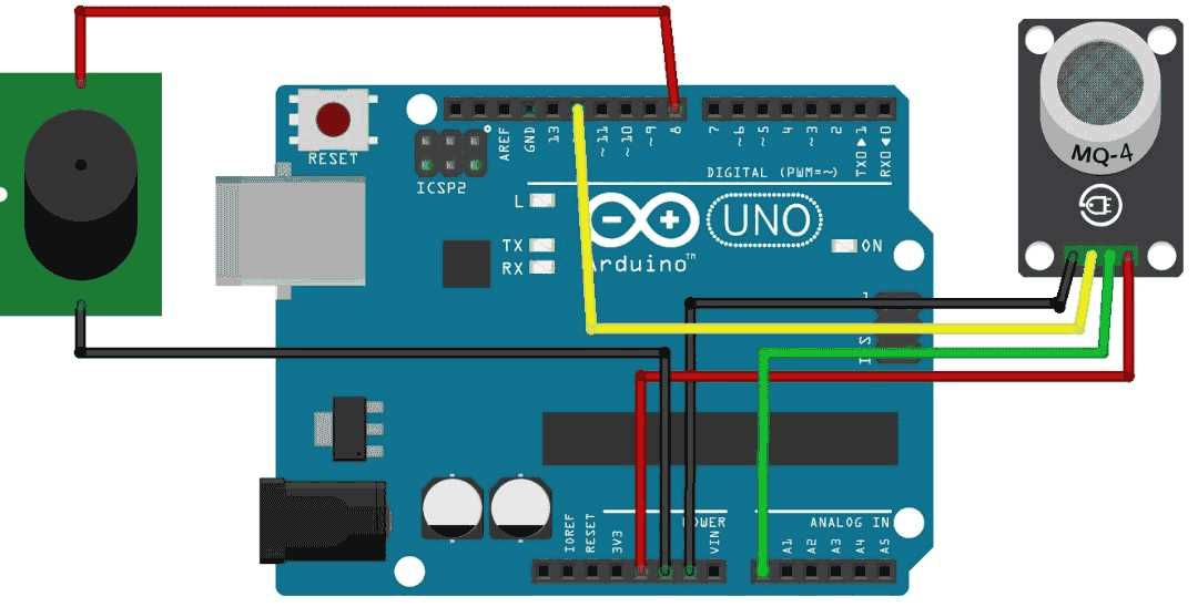
Connect the detection module through a voltage divider with a load resistor between 5 kΩ and 20 kΩ and supply the internal heater with a stable 5 V source capable of 150–200 mA. Semiconductor detection elements such as MQ-series devices change resistance depending on combustible or toxic vapor concentration. The output signal appears as a variable voltage that can be read by an analog input of a controller.
Guide to Wiring Christmas Lights for Safe and Effective Displays

christmas light circuit diagram

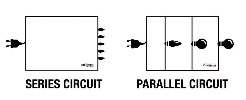
To ensure your festive decorations run safely, start by choosing the right configuration for connecting multiple bulbs. A common approach is the series connection, where the current flows from one bulb to the next. This method works well when you’re using a small number of bulbs and want a consistent, uniform display. However, make sure the voltage rating matches your power source to avoid overloading the system.

Clapp Oscillator Circuit Design and Operation Guide

clapp oscillator circuit diagram

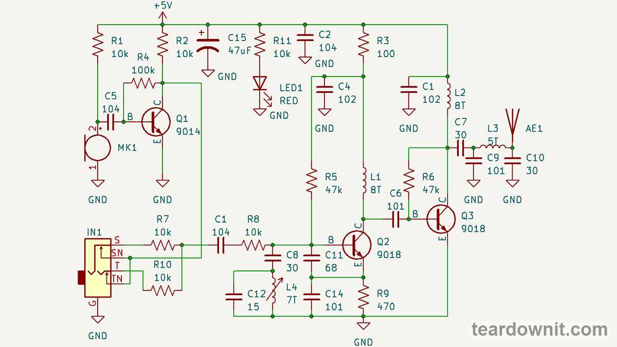
To design a stable frequency generator, start by understanding the core components involved. The basic setup requires a transistor, a feedback network, and a combination of capacitors and inductors. The frequency output is determined by the resonance of the LC tank circuit, which consists of these components. Pay careful attention to the values of the inductance and capacitance to ensure accurate frequency generation.

Wiring Guide for 12V Starter Solenoid

12v starter solenoid wiring diagram

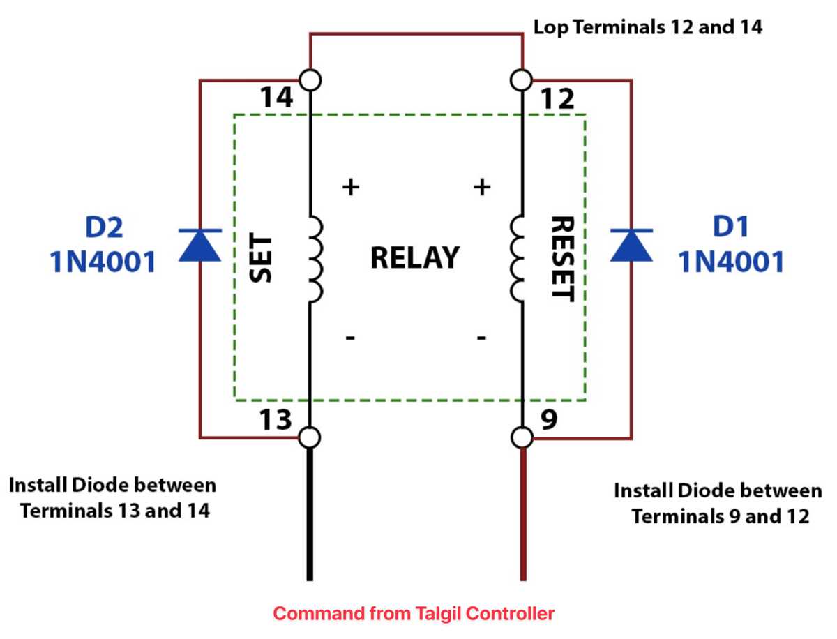
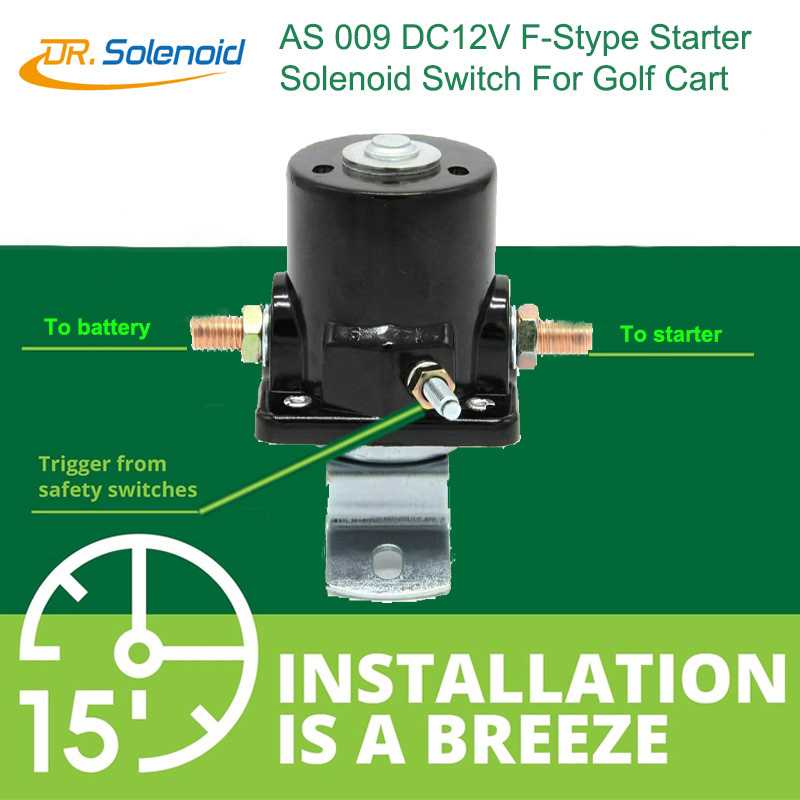
Begin by connecting the relay to the main power source. The positive terminal of the battery should be attached to the relay’s primary input terminal, while the ground connection should be securely grounded to the vehicle’s chassis or other grounded components. Ensure the battery is disconnected before proceeding to avoid electrical shock or short circuits.