Press "Enter" to skip to content

Category: other

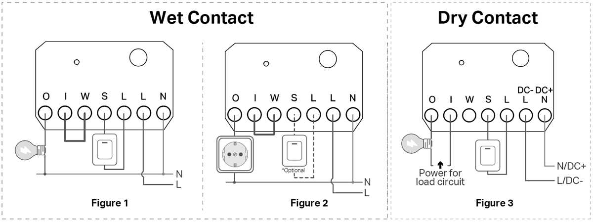
Understanding and Setting Up Dry Contact Connections

dry contact wiring diagram

To properly connect a relay for control systems, first identify the terminals on your switch. Typically, the common terminal (COM) connects to the input power, while the other two terminals, normally open (NO) and normally closed (NC), control the connection depending on the switch’s position. When the switch is open, the circuit remains off, and when closed, power flows through it.
27MHz Transmitter and Receiver Circuit Design and Setup

To build a reliable wireless communication system, start by selecting the correct frequency module for sending and receiving signals. Ensure the chosen module operates within the desired frequency range and has the proper power output to cover the required distance. The efficiency of the transmission relies heavily on the components used, so use high-quality capacitors and resistors to reduce noise and ensure a stable connection.

Air Handler Wiring Diagram With Terminal Layout and HVAC Control Wire Connections

Disconnect power at the breaker panel before opening the indoor HVAC cabinet. The blower unit and control board receive both high-voltage supply (usually 120 or 240 V) and low-voltage control signals around 24 V. Contact with energized terminals can damage equipment or cause injury, so power isolation is the first action before inspecting conductor routing.

Understanding the Components and Setup of a Branch Circuit

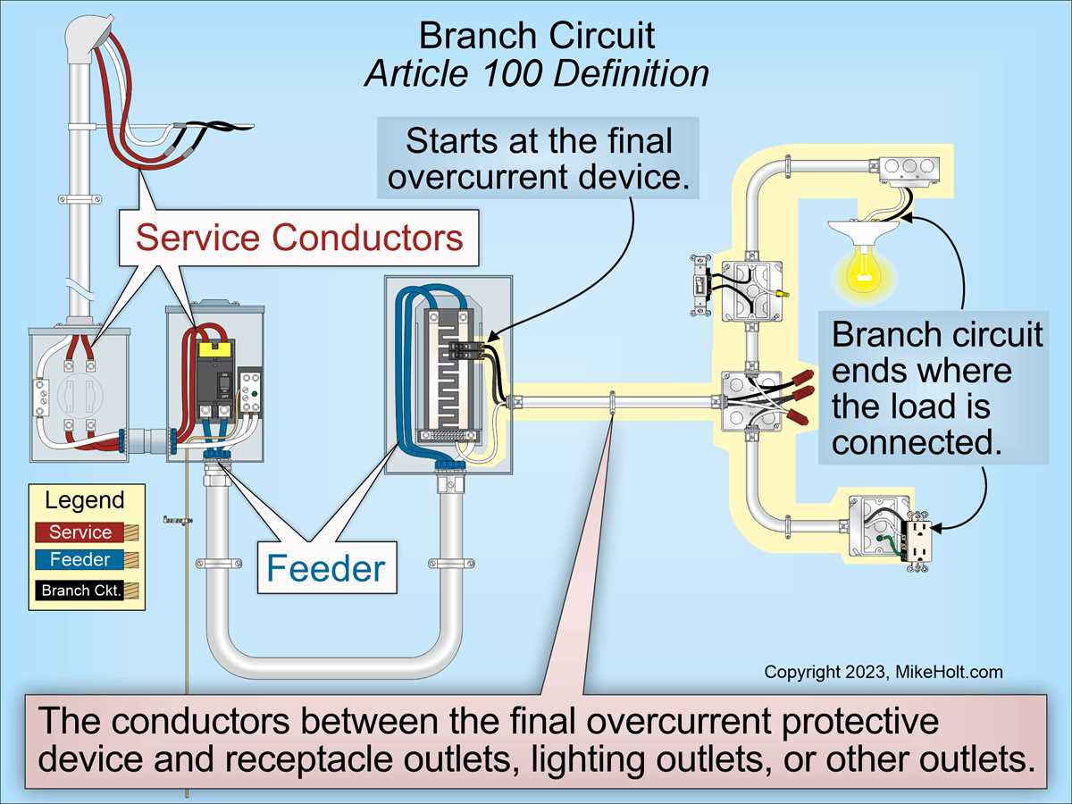
branch circuit diagram

To ensure a functional and safe electrical installation, begin by mapping out the overall power flow from the main panel to the various endpoints within the system. Identify all key components, such as protection devices, switches, and outlets, considering how they will be distributed across the entire installation. This initial step lays the foundation for planning wiring routes and load balancing.