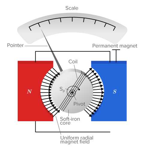
To design an accurate measurement tool for small currents, begin by selecting a sensitive needle movement mechanism. This typically involves choosing a coil that interacts with a magnetic field to create the desired deflection. The coil resistance and magnetic field strength are critical factors in determining the sensitivity of the device.
Next, ensure you choose the proper current-limiting resistors to prevent damage to the components from excessive flow. The resistors should be placed in series to limit the maximum current that can pass through the system, offering protection while still allowing for accurate measurements.
When assembling the system, proper calibration is required to match the movement of the needle with the applied current. Using known reference values, adjust the positioning of the needle and fine-tune the resistance values to ensure precise reading. This calibration step is vital for achieving reliable results in real-world applications.
Designing a Precision Measurement Device for Electrical Currents
Begin by selecting a coil that provides the required sensitivity. The coil interacts with a magnetic field, generating a force that moves the needle. The number of turns in the coil directly affects the sensitivity, so choose the optimal number to balance sensitivity and stability.
Choosing the Magnetic System
For the magnetic field, use a permanent magnet that creates a stable and uniform field. Ensure the magnet is positioned in a way that evenly distributes the magnetic field over the coil, providing consistent readings. Neodymium magnets are a good choice due to their strength and small size, which keeps the system compact and efficient.
The magnet’s strength should be carefully matched to the coil’s characteristics. Too strong a magnet may lead to excessive deflection, while too weak a magnet can result in inadequate movement. It’s important to test different strengths to achieve the correct balance for your application.
Incorporating the Measurement Scale
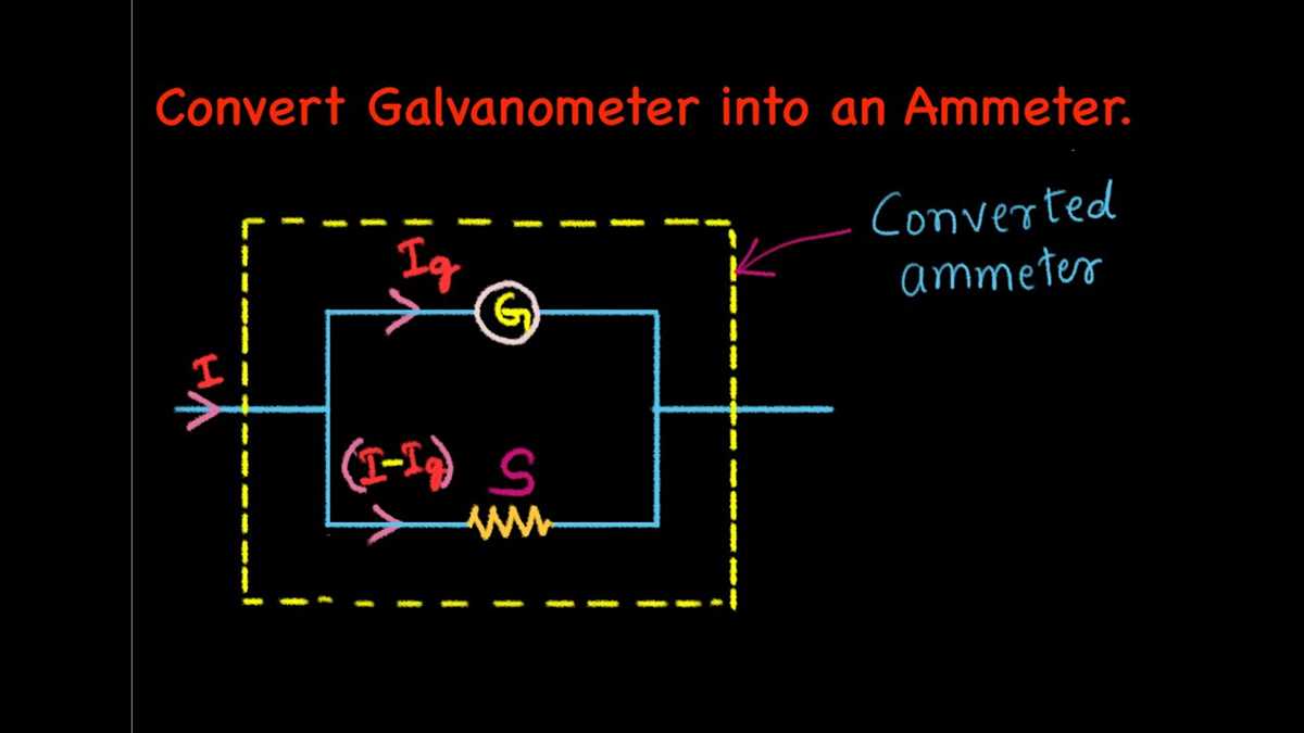
Install a graduated scale to the device’s display. The scale should be finely marked to allow precise readings, with each division corresponding to a specific value of current. The scale’s accuracy depends on the deflection range of the needle, so calibrate it with known current values to ensure the display matches the actual readings.
Place the needle on a pivot mechanism to allow smooth movement. The pivot must be low-friction, so using a jewel bearing or a similar high-precision bearing is recommended for minimizing any potential resistance that could affect accuracy.
Finally, ensure that the resistors used to limit the current are of high quality and rated for the power they’ll dissipate. Calculate the appropriate resistance to ensure the system operates within safe limits while providing accurate readings. Testing the device under different load conditions helps verify that the system performs well across a wide range of currents.
Choosing the Right Components for a Precision Measurement Device
Select a coil that can generate a strong deflection with minimal current. The number of turns in the coil impacts the sensitivity of the device; more turns increase the sensitivity but require more power. A balance between sensitivity and power consumption is necessary to ensure the system operates effectively.
Choosing the Proper Magnet
The magnet plays a key role in creating the magnetic field for needle deflection. A neodymium magnet is a good choice due to its strong field and compact size. Ensure that the magnet is positioned to create a uniform field across the entire coil, which helps maintain consistency in the readings.
The strength of the magnet should be selected based on the size of the coil and the desired range of deflection. If the magnetic field is too strong, the deflection may be excessive; if too weak, the needle may not move enough to provide a readable measurement.
Precision Resistors for Stability
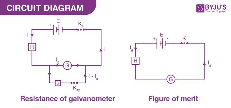
Include resistors that will limit the current flowing through the coil to prevent overheating. Precision resistors with a low tolerance ensure the system operates within the desired range without introducing noise or instability. Choose resistors with a power rating that matches the current expected through the system.
- Use resistors with high precision ratings for accurate readings.
- Ensure resistors can handle the expected power dissipation without heating up.
Consider adding a shunt resistor in series with the device to allow for easy calibration and prevent excessive current from damaging sensitive components. The shunt resistor helps in measuring the current flowing through the device, providing feedback for proper scaling.
Needle and Pivot Mechanism
The needle should be lightweight and balanced to ensure smooth movement. A finely balanced needle minimizes friction and prevents sticking, which could affect measurement accuracy. Use a fine, non-magnetic needle made from a material that won’t easily bend or deform under regular use.
The pivot mechanism must be low-friction to ensure smooth and responsive needle movement. Jewel bearings or precision needle bearings are ideal choices for their durability and minimal resistance. A well-designed pivot ensures that the needle moves freely without causing inaccurate readings due to mechanical resistance.
Calibration and Testing Components
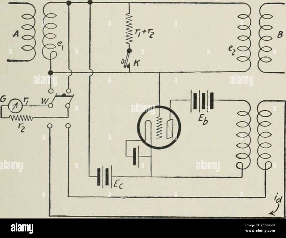
Finally, add calibration resistors to fine-tune the device’s accuracy. These resistors should allow for small adjustments in the measurement range. Use known reference currents to calibrate the system and ensure that the needle deflects correctly in response to different current levels.
Ensure the device is tested under various load conditions to verify that the chosen components function as expected. Adjust the magnet and resistor values as needed to achieve the desired accuracy across the full range of measurements.