Ensure the live conductor is always connected to the correct terminal to prevent short circuits or electrical fires. Use color-coded wires: brown or red for phase, blue for neutral, and green/yellow for grounding. Double-check connections before energizing the circuit.
Mount receptacles firmly within the junction box to avoid loose contacts. Secure all screws tightly and verify that the protective earth line makes continuous contact with the metal housing for maximum safety.
Follow sequence for multi-outlet setups: feed the main line through the first port, then branch additional lines in parallel, ensuring each path maintains the correct polarity. Avoid daisy-chaining multiple plugs without proper rating; it may overload the circuit.
Test each connection with a voltage detector before inserting any appliances. Even minor wiring mistakes can cause sparks, so confirm live, neutral, and ground lines are correctly aligned. Replace damaged wires immediately to maintain reliability.
Use terminal blocks or insulated connectors rather than twisting wires together. This prevents loosening over time and reduces the risk of arcing. Label each wire to simplify future maintenance and troubleshooting.
Wall Socket Wiring Diagram
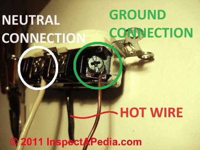
Connect the live conductor to the brass terminal, ensuring the screw is fully tightened to prevent overheating. Use 14-gauge copper wire for circuits rated at 15 amps and 12-gauge for 20-amp lines. Always strip precisely 10 mm of insulation to expose the conductor without nicking the metal.
Attach the neutral line to the silver terminal, maintaining consistent polarity throughout the installation. Color code the wire with white insulation for easy identification and verify continuity with a multimeter before securing the assembly.
Grounding requires a green or bare copper wire attached to the green screw on the metal frame. Confirm the continuity of the ground path to the main panel to avoid potential shock hazards. Avoid using aluminum wire for grounding connections.
When multiple outlets share a single circuit, use pigtail connectors to join wires before attaching them to terminals. This minimizes mechanical stress and prevents loose connections that could trigger arcing or tripping of breakers.
Ensure the mounting box is flush with the wall surface and free of obstructions. Tighten the retaining screws evenly to avoid warping the housing, which can interfere with proper insertion of plugs and compromise electrical contact.
After assembly, test the receptacle using a voltage tester under load. Measure both voltage and polarity to confirm correct installation. Document the position and configuration of each connection for future maintenance or upgrades.
Identifying Live, Neutral, and Earth Wires for Safe Connections
Use a non-contact voltage tester to confirm which conductor carries current before touching any terminals. Live wires typically display a reddish-brown or black insulation in most regions, while neutral conductors are blue or white. The protective conductor is usually green-and-yellow striped.
When inspecting an existing installation, always trace the wires back to the distribution board. Live lines should connect to the breaker output, neutral to the return bus bar, and the earth wire to the grounding terminal. Avoid assuming colors are correct; older systems may not follow modern codes.
For temporary identification, label each cable with masking tape and a permanent marker. Assign L for live, N for neutral, and E or the ground symbol for earth. This prevents confusion during reconnection, especially in multi-gang units or complex configurations.
Using Multimeters for Verification
Set a digital multimeter to AC voltage mode. Measure between suspected live and neutral; readings near mains voltage confirm the live conductor. Testing between live and earth should show the same voltage. Measuring neutral to earth should return zero or near-zero volts, indicating correct polarity.
Inspect insulation integrity visually and manually. Damaged sheathing, nicks, or exposed metal can create shorts or electric shocks. Replace compromised conductors before proceeding with terminals or clips.
When connecting, ensure that the live conductor enters the terminal marked with an “L,” neutral goes to “N,” and the protective conductor to the grounding point. Tighten screws firmly; loose contacts can cause sparks or heating, leading to fire hazards.
After installation, test the circuit using a plug-in tester or multimeter. Confirm that the device functions correctly and that no voltage appears on the metallic body, ensuring the earth connection is continuous and reliable.