Press "Enter" to skip to content

Category: other

Schematic Circuit Diagram Symbols Layout Rules and Methods for Reading Electrical Schematics

schematic circuit diagram

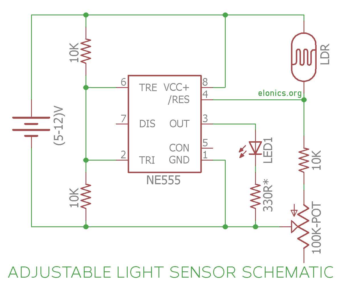
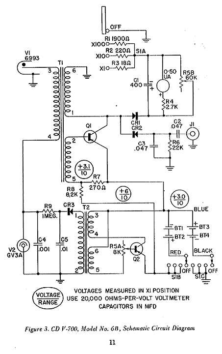
Identify the power source, ground reference, and signal flow before examining any electrical drawing. This quick scan helps determine how energy enters the system, where it returns, and how components interact along the path. Without this orientation, interpreting symbols and connections becomes confusing and time-consuming.
Understanding Microprocessor Circuit Diagrams and Their Key Elements

microprocessor circuit diagram

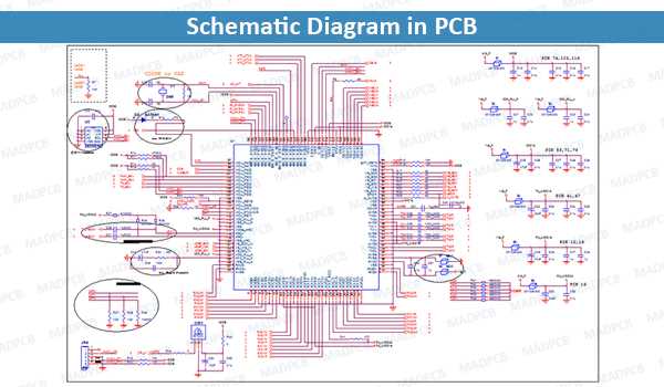
To understand how a processor works, you need to be able to interpret its blueprint. A processor’s schematic reveals the connections and relationships between various components such as memory, buses, and control units. Begin by identifying the main elements, such as the processor pins, voltage supplies, and clock signals, which are typically the starting points for a clear understanding of the processor’s functionality.

Stop Turn Tail Light Wiring Instructions and Diagram

To connect the rear electrical system of your vehicle, it’s critical to understand the exact connections for the brake, turn, and rear markers. Properly wiring these circuits ensures safety and compliance with road regulations. Start by identifying the correct wire colors: typically, the brake light uses a red wire, while the turn signal is often indicated by a yellow wire. The rear marker is usually wired with a brown or clear wire.