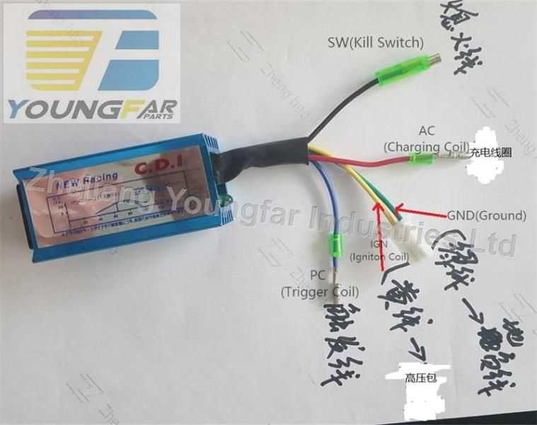
Ensure each conductor is matched with the corresponding engine component according to its color code and function. Red wires typically carry positive current, while black or green wires serve as ground connections. Incorrect attachment can prevent ignition or damage sensitive electronics.
Use a multimeter to verify continuity before final attachment. Signal output wires should be checked for proper voltage pulses during engine rotation. This step avoids misfiring and maintains reliable spark timing.
Secure all terminals with proper connectors and ensure insulation covers are intact. Loose contacts can cause intermittent firing or erratic engine performance. Double-check that connectors are free from corrosion and moisture intrusion.
5 Terminal Ignition Control Connection Guide
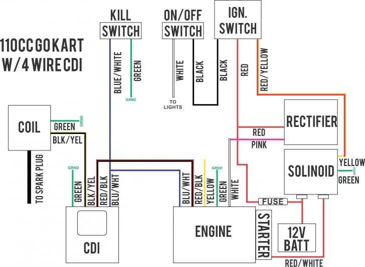
Connect the red lead to the positive supply from the battery and ensure it carries steady voltage without fluctuation. Attach the black or green lead to a solid ground point on the engine frame to avoid intermittent sparking. The remaining three leads must match the stator, trigger coil, and ignition coil terminals precisely to maintain proper timing and avoid misfires.
Check each connection with a multimeter before running the engine. Signal leads should register consistent voltage pulses during engine rotation, while output leads should deliver sparks reliably under load. Secure connectors with insulated covers to prevent corrosion and vibration-related disconnections, ensuring continuous engine operation under all conditions.
Identifying Terminal Functions and Color Codes
Verify the role of each lead before connecting to avoid engine misfires. Red wires typically supply continuous voltage from the battery, while black or green wires serve as the main grounding path. Signal leads from the stator or trigger coil often appear in yellow or blue and must match the corresponding engine inputs exactly for accurate ignition timing.
Follow this checklist for precise identification:
- Red – positive voltage supply
- Black/Green – engine ground connection
- Yellow – pulse input from the trigger coil
- Blue – connection to ignition coil or output module
- White – auxiliary or timing adjustment signal
Confirm each lead with a multimeter reading under rotation conditions to ensure proper function before sealing connections.