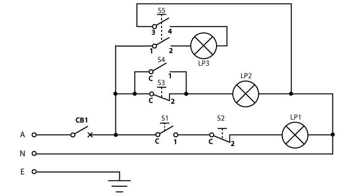
Check the circuit layout drawing before installing any cable or device. A clear electrical scheme prevents wrong connections, overloaded lines, and wasted time during installation. Builders and technicians rely on such drawings to see where conductors run, how switches control lighting points, and which breakers protect each circuit. Without this visual reference, tracing connections inside walls becomes slow and error-prone.
An electrical layout sketch shows routes of conductors, connection points, switching elements, and protective devices. Standard symbols represent outlets, lamps, distribution boards, and control switches. For example, a single-pole switch is usually marked with a simple break in the line, while a ceiling light appears as a circle with a cross. These signs allow electricians from different teams to read the same drawing without written explanations.
Accurate electrical sketches also support load distribution. A residential lighting circuit often uses a 10–16 A breaker, while socket groups commonly connect through 16–20 A protection. When each branch is marked clearly on the circuit sketch, installers can see which outlets share the same line and avoid exceeding the allowed load for copper conductors such as 1.5 mm² or 2.5 mm².
Clear connection maps are used during design, installation, and maintenance. If a switch stops controlling a light or a socket loses power, technicians compare the real installation with the electrical scheme. This comparison helps locate junction boxes, hidden cable routes, and branching points without removing large sections of wall finishing.
Wiring Plan Diagram Guide With Symbols Layout Rules and Practical Reading Tips
Read the symbol legend before tracing any conductor path. Electrical layout drawings rely on standardized signs that show switches, lighting points, outlets, and protection devices. A small square may indicate a wall socket, a circle with a cross marks a ceiling lamp, and a broken line with a pivot sign shows a single-pole switch. Understanding these marks allows a technician to follow power flow from the distribution board to the final device without guessing connection routes.
Follow the conductor path step by step from the electrical panel. Power usually leaves the panel through a circuit breaker, enters a junction box, and then branches toward switches and loads. When reading a circuit sketch, track the line direction and junction points. Pay attention to conductor crossings: a crossing without a dot usually means the lines pass without contact, while a filled dot indicates a real connection. Correct interpretation avoids mistaken linking of circuits that must remain separate.
Typical graphical signs used in electrical layouts
- Circle with cross – ceiling lighting point
- Small rectangle or square – wall socket outlet
- Broken line with pivot mark – single-pole switch
- Two parallel lines – double socket outlet
- Box with multiple branches – junction box
- Rectangle with rating value – circuit breaker in the distribution board
Practical reading tips for electrical layout drawings
- Locate the distribution board first and identify all outgoing circuits.
- Trace each conductor route from protection device to load.
- Check branch points inside junction boxes for circuit splitting.
- Confirm switch control lines leading to lighting points.
- Compare conductor size notes such as 1.5 mm² for lighting or 2.5 mm² for socket circuits.
Use conductor labels and breaker ratings to understand load distribution. Lighting circuits often connect through 10–16 A breakers with 1.5 mm² copper lines, while outlet groups commonly use 16–20 A protection with 2.5 mm² conductors. By matching these markings with the circuit layout drawing, technicians quickly identify which outlets share the same branch and which lighting points are controlled by a specific switch.
Common Symbols Used in a Wiring Plan Diagram and What Each One Represents
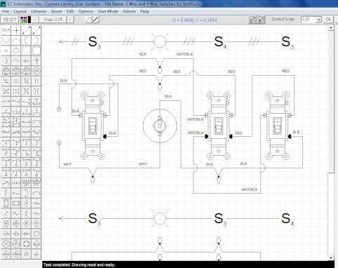
Identify the symbol legend before analyzing any electrical layout drawing. Standard graphic signs replace long descriptions and allow electricians to read a circuit scheme quickly. These marks show outlets, switches, lighting points, protective devices, and connection boxes. Each symbol represents a physical component installed in walls, ceilings, or electrical panels.
A ceiling light is usually shown as a circle with a cross inside. This mark indicates the position of a lighting fixture connected to a switch or control line. Wall-mounted lamps may appear as a semicircle attached to a wall line. If multiple lamps connect to the same switch, several circle symbols appear along a single conductor route branching from a junction box.
Socket outlets appear as small squares or rectangles placed along room walls in the electrical layout sketch. A double outlet may include two parallel lines or duplicated marks inside the square. Some drawings add a grounding indicator beside the outlet symbol, showing that the device connects to a protective earth conductor. These marks help installers position outlets at correct heights such as 300 mm above the finished floor for general sockets.
Switches use simple break symbols inserted into a conductor line. A single-pole switch often looks like a short angled line touching the conductor path. A double switch includes two control marks branching from the same location. This visual difference shows that two lighting circuits can be controlled from the same wall box. Three-way or staircase switches usually include additional arrow marks indicating multi-point control between two locations.
Junction boxes and distribution boards appear as rectangular shapes with several conductor lines entering or leaving the symbol. These boxes represent connection points where multiple cable runs join together. Circuit breakers inside the electrical panel are typically drawn as rectangles labeled with ratings such as 10 A, 16 A, or 20 A. By reading these marks on the circuit scheme, a technician understands which protective device supplies each lighting or socket branch.