
The first step in creating a functional electronic system is understanding the various visual representations used to convey electrical connections. These visuals, which represent the physical layout and flow of current through components, are crucial in designing and troubleshooting any device. The most common forms include schematic, block, and wiring layouts, each serving a unique purpose in conveying system information.
For example, a schematic view is ideal for representing how components like resistors, capacitors, and transistors connect, while a block model offers a simplified version of a system, highlighting functional sections without going into minute details. When you’re setting up or repairing a device, knowing which diagram to use can drastically improve both your comprehension and efficiency.
Each of these illustrations has its specific uses, from basic educational purposes to high-level engineering designs. As you gain familiarity with the layout conventions, you’ll be able to identify and implement each with precision. In the following sections, we’ll break down these common formats and help you decide when and how to apply them for maximum effectiveness.
Different Types of Circuit Diagrams
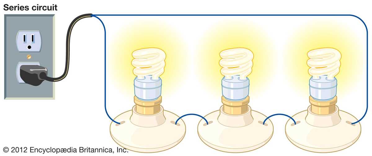
A schematic is the most common representation for showing the connections between components in an electrical setup. It uses standard symbols for components like resistors, capacitors, and transistors, allowing anyone familiar with the symbols to understand the system’s operation. This type is particularly useful for designing and analyzing circuits on a component level, providing an accurate and clear view of how everything is interconnected.
A block diagram simplifies complex systems by representing functional units rather than individual components. This type is often used to show higher-level concepts, such as how a device or system performs specific tasks, without focusing on the detailed internal connections. Engineers and designers use block diagrams in the initial stages of design to conceptualize the overall flow and functionality of the system.
Wiring diagrams, on the other hand, provide a more practical view, showing how actual wires are connected in a physical setup. This format is crucial when setting up or repairing systems, as it shows the specific routes that connections should follow. Unlike schematic diagrams, wiring layouts are more intuitive for hands-on assembly and troubleshooting, as they reflect the real-world arrangement of components and wires.
How to Identify and Interpret Schematic Diagrams
To interpret a schematic representation, start by identifying the common symbols for each component, such as resistors, capacitors, and diodes. These symbols are standardized, so once you know them, you can quickly recognize how each part functions in the system. Follow the lines connecting the components to understand how current or signals flow through the circuit. Make sure to examine the power sources, ground connections, and any control elements like switches or microcontrollers that might dictate the behavior of the setup.
Next, pay attention to the labels and values marked on the diagram. For instance, resistors might be labeled with their resistance value, while capacitors will show their capacitance. This information is crucial when building or troubleshooting a system, as it tells you what specifications each component must meet. When analyzing the circuit, ensure you’re following the correct path from start to finish, noting how each connection affects the overall function.