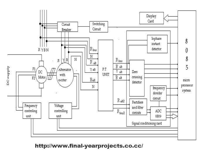
To understand how a processor works, you need to be able to interpret its blueprint. A processor’s schematic reveals the connections and relationships between various components such as memory, buses, and control units. Begin by identifying the main elements, such as the processor pins, voltage supplies, and clock signals, which are typically the starting points for a clear understanding of the processor’s functionality.
When examining the design, pay close attention to how different modules communicate with each other. For example, the data path will show how information moves from one part of the system to another, while the control lines dictate how the processor handles and processes tasks. Studying these pathways can provide valuable insight into how instructions are executed and how various operations are carried out.
If you’re just starting out, focus on recognizing the power rails, reset circuits, and the main data flow. As you become more comfortable, try to map out the connections between the processor’s internal components and how external devices interact with it. This will make it easier to diagnose problems or optimize designs in future projects.
Understanding Processor Layouts
Begin by identifying the core building blocks: power supplies, control lines, and data buses. The first step in interpreting a processor’s blueprint is recognizing how power is distributed across the device. Look for voltage rails and ground points to ensure the processor will function properly under varying conditions. It is important to understand that these lines provide the necessary electricity for the entire setup, and without them, no other components will work.
Once the power setup is understood, focus on the data flow. Typically, processors have a series of data buses that manage the movement of information between components. Look for the bidirectional paths that transfer data from the memory unit to the processing unit, and how they are routed throughout the design. It is important to analyze how these routes are organized to optimize both speed and accuracy of the information being transmitted.
Next, examine the control system. This part of the setup governs the operation of the processor, deciding which instructions are executed, and when. The control unit often has direct links to the memory system, and understanding how they interact will give you insight into how data is processed and handled in real-time. Take note of any clock signals or timing circuits that synchronize the entire process.
- Ensure correct alignment of control signals and data paths.
- Double-check connections for any potential feedback loops or short circuits.
- Pay attention to inter-component communication lines, which play a role in both speed and functionality.
Lastly, once all the elements are identified, work on troubleshooting common issues that arise in these systems. A common problem can be traced back to the failure of a single control or data line, which could prevent the processor from functioning as intended. Verifying the correct routing of these connections and ensuring no overlapping or conflicting signals are essential steps in building a stable and reliable setup.
How to Read a Microprocessor Circuit Diagram
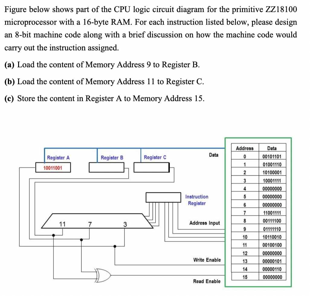
Begin by identifying the key components in the blueprint, such as power supply, memory connections, and control lines. Pay attention to the lines that represent power rails, which distribute electricity throughout the system. Look for voltage input points and grounding, as these are critical for the proper functioning of the system. Once you understand the power setup, focus on the paths that allow data transfer between components. These data lines typically link the memory unit to the processing core, and their flow will show how information moves through the device.
Analyzing Data Flow and Control Lines
Next, focus on the control lines that manage the flow of instructions within the system. These are usually connected to clock signals and timing mechanisms that ensure the processing of tasks happens in a synchronized manner. Examine the relationships between different components and how they communicate with each other. A well-drawn schematic will clearly indicate which components are interacting at any given moment, making it easier to follow how tasks are executed. Look for connections that show how the processing unit accesses and manipulates data in real time.